


HIRF Test Methodology
The final stage of aircraft clearance may involve limited illumination of the aircraft with threat level RF fields, typically over the range 10 kHz – 18 GHz. As an alternative approach, with lower facility costs than for testing the total aircraft with threat simulators, the following methodology is being increasingly used
Measure the coupling of EM energy (transfer function)
Measure the coupling of EM energy (transfer function) into the interior of the aircraft over the total frequency band of all the environments by illuminating the aircraft with low level swept continuous wave (CW) radiated fields. These measurements are normally made in “free field” conditions. Where the transfer function is in terms of the external field to the internally induced cable bundle currents it is known as the Low Level Swept Current (LLSC) test (Figure 1) and when it is in terms of the external field to the internally induced fields it is known as the Low Level Swept Field (LLSF) test (Figure 2).
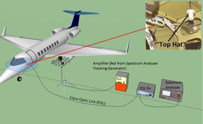
FIG.1 – Test Arrangement for the LLSC Test (nose antenna omitted)
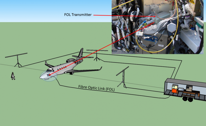
FIG.2 – Test arrangement for the LLSF test
STEP 1 – Compute currents or internal fields from coupling measurements
Use suitable signal processing algorithms and compute from the coupling measurements the currents (100 MHz) at the equipment’s location, that would be induced by the HIRF environments on the wiring systems.
STEP 2 – Directly inject predicted threat currents or irradiate the equipment and its wiring
Directly inject the predicted threat currents on the wiring systems, or at higher frequencies (>400MHz), irradiate the equipment and its wiring being assessed with predicted threat fields. Appropriate modulation is applied to simulate emitter parameters. This testing can be applied at system rig level (alternatively termed the systems integration facility), providing the rig is an accurate representation of the aircraft system.
STEP 3 – Use current probes and broadband antennas
Cable bundle currents can be measured using small ferrite current transformers or probes. The internal fields can be measured using small broadband antennas, such as the “Top Hat” biconical 1- 18 GHz receive antenna shown in Figure 2. Signals from the current probes/antennas are coupled back to the remote instrumentation using analogue FOLs to as high a frequency as possible. Multi-channel FOLs, such as the PPM Sentinel 3 cover frequencies up to 3GHz. Above this frequency, cables are used with great care to ensure they don’t compromise the integrity of the airframe shielding being assessed.
The future of HIRF testing with FOLs
Future fibre optic technology will likely permit reliable FOLs to be developed to cover the full low level swept coupling range of 10kHz to 18GHz. This would dramatically improve the measurement dynamic range as such high frequency FOLs would remove the cable losses which become large above 1GHz due to the cable lengths involved. As an example, even low-loss microwave signal cables have loss figures of typically 1 dB/metre at 18GHz.
Per maggiori informazioni contattaci: https://www.lunitek.it/contatta-sensoristica-e-acquisizione-dati/