


Remotely Reprogrammable Sensors for Structural Health Monitoring
S.W. Arms, J.H. Galbreath, A.T. Newhard, C.P. Townsend
Abstract
Wireless sensors can improve our ability to monitor critical civil infrastructure, including highways & bridges. We have previously reported on highly miniaturized, wireless strain, acceleration, and inclination sensing systems capable of providing low & high speed data update rates. Signal conditioning, multiplexing, A/D conversion, processing, amplifying, data logging, and bi-directional wireless communications are fully integrated. Each node includes a unique address (RFID), allowing a single base station to orchestrate data collection from thousands of distinct sensing nodes.
In order to enhance these capabilities, we have produced a new base station with remote cellular telephone interface. This allows access to the sensing network from anywhere where cellular communications are available. Key operating parameters such as triggering, data sampling rates, data sampling duration, continuous streaming duration, and number of active channels may all be programmed remotely. The base station can issue broadcast commands, such as “wake up, begin data logging, or “go back to sleep”. Node specific commands include “download data from node,
remove offsets from a node’s channel, increase gain on a node’s channel”.
These capabilities allow a remote sensing network to be deployed in the field and remotely adapted over time to meet the customer’s unique SHM requirements.
Introduction
Sensors integrated into structures, machinery, & the environment, coupled with the efficient delivery of sensed information, could provide tremendous benefits to society. Potential benefits include: fewer catastrophic failures, conservation of natural resources, improved manufacturing productivity, improved emergency response, enhanced homeland security. Wireless sensing networks can greatly reduce the costs associated with structural health monitoring, because they greatly reduce installation time and cost. The ideal wireless sensor is networked & scaleable, consumes very little power, is smart & software programmable, capable of fast data acquisition, reliable & accurate over the long term, costs little to purchase & install, and requires no real
maintenance [1].
The ability to modify the operating parameters of a wireless sensing network after installation can be critical to success. For example, the triggering parameters of a given sensing node or nodes on the network may need to be modified to accommodate changing strain levels, strain rates, vibration levels, or other operating conditions of the structure. The end user should be able to reconfigure
the installed wireless sensing nodes without being forced to directly connect to each node. The ultimate convenience is to provide the end user with the capability to reconfigure the wireless sensing network without leaving their office.
Objective
The objective of this paper is to describe the methodology used to develop a modular wireless sensor network capable of wireless reprogramming over a long distance cellular phone network. This system would allow an end user to gain control over a complete wireless sensing network from their office – from distances of thousands of miles away from the monitoring site where the sensing network is actually deployed. A concept drawing is provided in Figure 1, below.

Figure 1. Wireless strain sensing nodes distributed over the structure report data to one or more base stations located near the structure. A cellular phone link from the base station allows the sensing network to be controlled and re-programmed to meet the needs of the application from an office located anywhere in the world.
Methodology – Wireless Sensing Node
A functional block diagram of a versatile wireless sensing node is provided in Figure 2, below. A modular design approach provides a flexible and versatile platform to address the needs of a variety of applications. For structural health monitoring (SHM) applications, wireless tri-axial accelerometer nodes and wireless multi-channel strain gauge nodes are frequently deployed. Wheatstone bridge sensor input offsets may be removed using software commands. Bridge completion resistors for quarter and half bridge strain sensors may also be included, allowing a wide variety of strain gauges installations to be accommodated. Modules may also provide software programmable gains.
The bi-directional radio link may be reconfigured in software (frequency and RF power levels) as required for given applications’ wireless range requirement and in order to conform to specific radio communications standards for a particular region of the world. Each node contains a unique 16 bit address within its non-volatile memory. This scheme allows up to 65,536 (2^16) wireless sensing nodes to be deployed on the wireless sensor network. An important strategy to save power is to remotely command the wireless sensing nodes from a base station as required by the specific application. We have previously reported on addressable, wireless strain sensing nodes that respond to base station broadcast address and/or node specific address commands, including commands to sleep, wake up, log data, and stream data continuously [2,3]. However, our previous base station designs could not be controlled from a remote personal computer platform using cellular phone networks.
These addressable sensing nodes feature two Megabytes of on-board, non-volatile memory for data storage, 2000 samples/second/channel logging rates, 1700 samples/sec/channel over-the-air data rates, bi-direction RF link with remote offset and gain programmability, compact enclosure, integral rechargeable Li-Ion battery, and on-board temperature sensor. Figure 2 provides a photograph of a wireless strain sensing nodes packaged within an IP67, NEMA 4X rated environmentally sealed outdoor enclosure. The package includes neodymium magnetic mounts to provide easy mounting to steel structural elements. Cable glands allow lead wires from multiple strain gauges to enter the enclosure while maintaining the integrity of the water tight seal. We have used weldable strain gauges (350 ohms, quarter bridge, Micro-Measurements) with good success. These gauges are well protected from the environment and can be installed very quickly using a portable, battery powered spot welder.
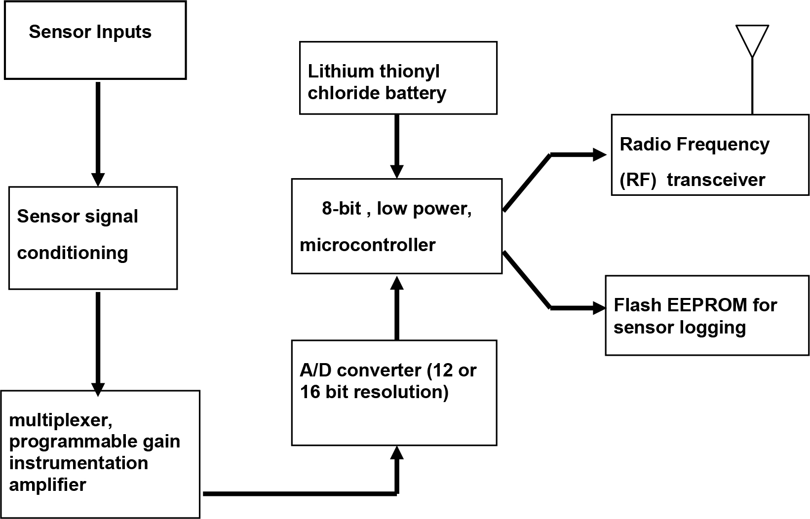
Figure 2. Wireless Sensor Node Block Diagram
Base Station Software Interface
In order to facilitate data collection, triggering, and programming of the wireless sensing nodes, a base station was placed on the structure within 160 meters (500 feet) of the sensing nodes. Figure 3 also depicts the Base Station, which was housed in a heated NEMA 4X enclosure and contained a digital radio receiver with RS-232 output, Panasonic “Toughbook” personal computer (PC), 802.11b WiFi card with PCMCIA interface to the notebook PC, and cellular telephone with modem interface. The base station was connected to a local power source (110 VAC) through an uninterruptible power supply to prevent loss of power during temporary outages and to protect against power drop out and/or surges. The system was deployed on a large civil structure in North America: the Ben Franklin Bridge, spanning the Delaware River from Camden NJ to Philadelphia, PA.
The system was designed to acquire strain data when trains passed on the bridge, but this required that the trigger levels be optimized for each strain sensor placement. The WiFi card allowed us to gain control of the system from under the bridge, which proved helpful when the triggering parameters were initially set up. The cellular phone interface was intended to provide a greater level of programmability and distant (remote) access into the wireless sensing network. The cell phone interface also allowed data to be copied or moved from the notebook computer platform on the bridge to another computer (or server) located on the local area network where another cell phone was used to establish the connection. The following figures (nos. 4-9) are screen shots from the Base Station (PC side) and “Strain Wizard ™ ” software used to configure & calibrate the nodes remotely, using bi-directional wireless communications as required for an SHM applications. The software was written for use on Windows 95/98/2000/XP platforms.
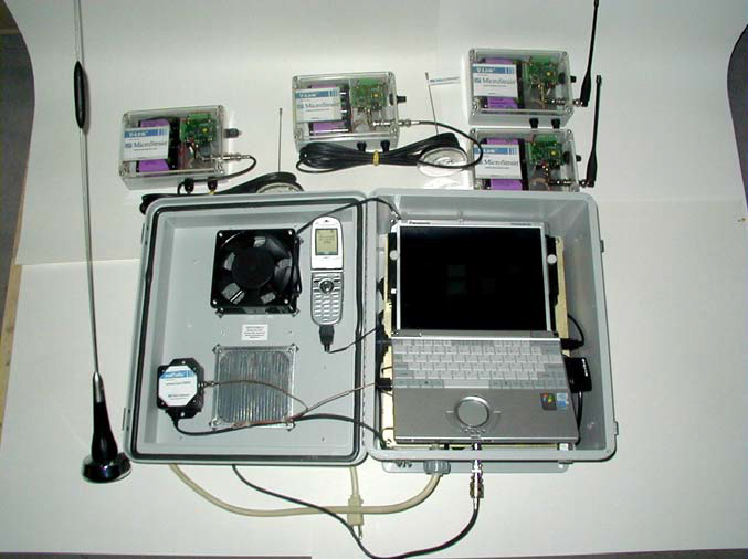
Figure 3. Wireless Sensing Nodes (4) in sealed NEMA 4X enclosures (top of photo). Base Station with Panasonic Toughbook ®, cell phone, 802.11b WiFi card, and narrowband RF Transceiver as packaged within sealed, thermally controlled enclosure (at bottom of photo).
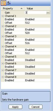
Figure 4. Software interface (on right) used to manually set up the number of active channels, as well as the offset and gain values for specific sensors on a channel-bychannel basis. The end user can also request that the software “sample” a specific channel on the wireless node to obtain an instantaneous snapshot.
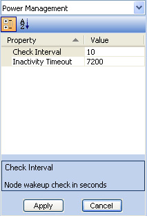
Figure 5. Software interface (on left) used to control sleep intervals between checks for commands from the base station. The inactivity timeout allows the node to go into micropower sleep mode if no commands or event triggers are detected.
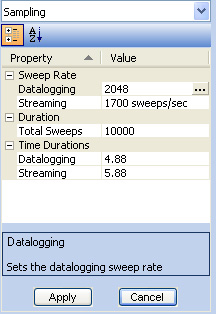
Figure 6. Software interface (on right) used to set up the sampling parameters of a specific wireless node on the network, specifically the sweep rate and total number of sweeps. The program automatically calculates the duration of the sample based on these two parameters for both data logging and streaming modes.
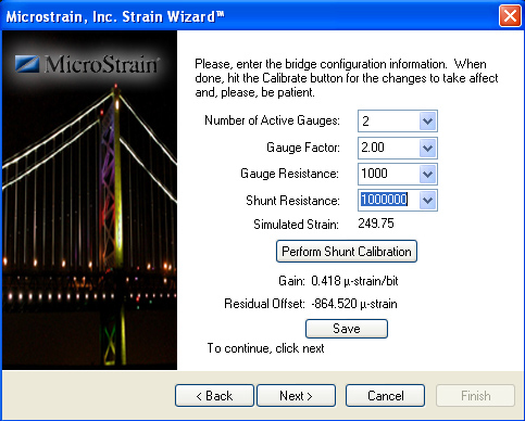
Figure 7. Software interface to provide the user with requisite gain and offset values after the remote balancing & shunt calibration steps have been performed.
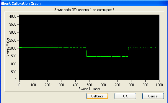
Figure 8. Software interface to indicate results of remote (wireless) shunt calibration of a specific node on the wireless network. In this case, node 25 has been shunt calibrated.
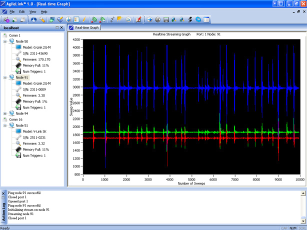
Figure 9. Software interface to display real time streaming data on a continuous basis from a specific node on the wireless network. In this case, node 91 reports in real time.
Cellular Telephone Link
Integration of cell phone and PC display redirection technologies provide remote base station control and node configuration options wherever cell phone coverage is available. The remote connection software engages in directly connecting to the internet based on the Microsoft Task Scheduler (Redmond, WA). This scheduling software allows the user to define when an internet connection should be established in a myriad of schemes ranging from set intervals such as weekly, daily, or hourly or exact time and date instances such as every second month at three in the morning.
During each connection session, an email is sent to a list of recipients containing detailed information on the base station’s internet location. This email list remains persistent amid system reboots as the list remains stored in the Window’s system registry and is editable via the remote data acquisition software. The user is provided with a window of opportunity (15 minutes) to connect to the base station, at which time they may cancel the automatic disconnect event and remain linked to the base station for as long as they desire. Connecting to the base station is executed through the use of remote display redirection software titled RealVNC; software initially developed by AT&T Laboratories in Cambridge, England and now available as open source. Through the assistance of this virtual network computing software, the user may operate on any aspect of the wireless network available to them as though they were physically in front of the base station’s PC. Upon expiration of the allotted connection window with no connection establishment or an explicit disconnect by the user, the cell phone line severs its link and attempts internet connection at its next scheduled time.
Discussion
A versatile wireless sensing system with remote reprogramming capabilities has been built and demonstrated. The graphical user interface may be controlled remotely using a cellular telephone interface. This system has potential to be used for advanced, remote condition based maintenance & structural health monitoring for a wide variety of machines and civil structures. A full system installation including ten wireless strain & temperature sensing elements, and two cell phone enabled base stations has been completed on the Ben Franklin Bridge, which is a major span crossing from Camden NJ, to Philadelphia, PA (Figure 10, below). The bridge is remotely accessible via remote software as described in this paper and is currently reporting strain data when passenger trains cross the bridge.

Figure 10. The Ben Franklin Bridge spans the Delaware River, with ten strain sensors periodically checking strain levels on a continuous basis at ~1 Hz sample rates. The presence of a passenger train creates a change in strain rate, which triggers automated data acquisition at 32 Hz sample rates by the wireless strain sensing nodes.
REFERENCES:
1. Arms, S.W., Townsend, C.P. (2003): Wireless Strain Measurement Systems, Applications & Solutions, Presented at NSF-ESF Joint Conference on Structural Health Monitoring Strasbourg, France
2. Galbreath, J.H, Townsend, C.P., Mundell, S.W., Hamel M.J., Esser B., Huston, D., Arms, S.W. (2003): Civil Structure Strain Monitoring with Power-Efficient High-Speed Wireless Sensor Networks, Proceedings International Workshop for Structural Health Monitoring, Stanford, CA
3 Townsend C.P, Hamel M.J., Arms S.W. (2001): Telemetered Sensors for Dynamic Activity & Structural Performance Monitoring, SPIE’s 8th Annual Int’l conference on Smart Structures and
Materials, Newport Beach, CA
ACKNOWLEDGEMENTS:
The authors are grateful for the partial support from the National Science Foundation’s SBIR program. We also want tothanks to the Delaware River Port Authority in Camden, N.J., which provided us with the opportunity to demonstrate our systems on the Ben Franklin Bridge.
Per maggiori informazioni contattaci: https://www.lunitek.it/contatta-sensoristica-e-acquisizione-dati/