OXTS – Indoor positioning with Locata case study: automated vehicle safety testing in indoor and GNSS-challenged environments

OXTS – Indoor positioning with Locata case study: automated vehicle safety testing in indoor and GNSS-challenged environments


Indoor positioning with Locata case study: automated vehicle safety testing in indoor and GNSS-challenged environments

Introduction

Designing and executing the necessary tests to develop, evaluate and compare advanced driver assistance systems (ADAS) and autonomous driving functions is posing an ever-growing dilemma to the automotive industry. The test setup must be repeatable and as independent as possible of time of day, weather conditions and test driver behaviour.

One such organisation facing up to the challenge is the Insurance Institute for Highway Safety (IIHS), and independent American body conducts which tests to assess how ADAS technology can prevent or lessen the severity of crashes. Several years ago IIHS identified a growing need to expand its test facilities while meeting the requirements for future testing, including all-weather operation and test automation.

In 2015 IIHS completed a $30 million expansion of its Vehicle Research Center (VRC), the centrepiece of which was a five-acre covered track designed to allow testing to continue in all weathers. An existing outdoor track was also expanded, bringing the total area of test track to 15 acres. Given the need to simulate crashes safely, accurately and repeatably, IIHS had also researched robotic equipment to automate some of the driving tasks.

While the covered track offered much needed all-weather testing capability, it introduced a challenge for the high-accuracy GNSS-INS measuring equipment that IIHS uses for testing. IIHS operates a multi-frequency GNSS base station with real-time corrections to provide the position, velocity and time (PVT) parameters that are required for testing and essential for operating robotic test equipment. However, tests on the covered track showed the equipment was not delivering the accuracy and repeatability needed, and it was concluded that the steel trusses of the covered track’s fabric roof were obstructing the GNSS signals. Finding an alternative positioning technology that could deliver the required positioning performance on both the open and covered tracks triggered a global technology search.

Locata

In 1997 Australian company Locata began developing an alternative to GNSS/GPS in order to overcome the limitations of satellite signal-based navigation systems while delivering centimetre-level accuracy. Key to Locata’s system is a time-synchronization capability, called TimeLoc, that allows its ground-based signal transmitters, known as LocataLites (LLs), to synchronize with each other to picosecond precision.

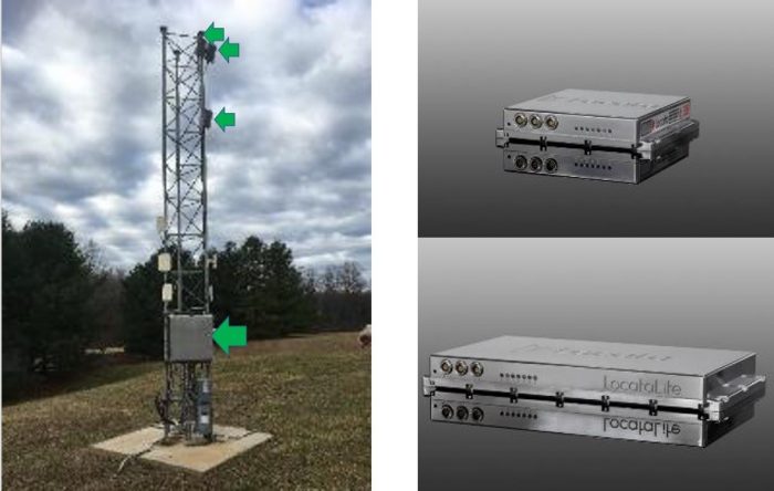
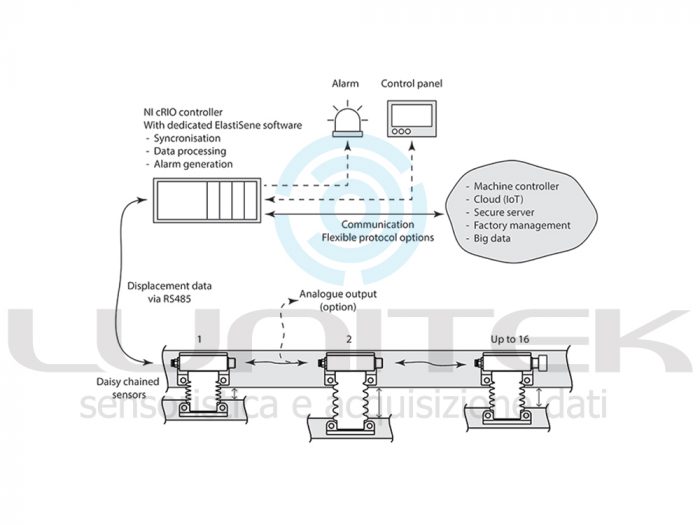
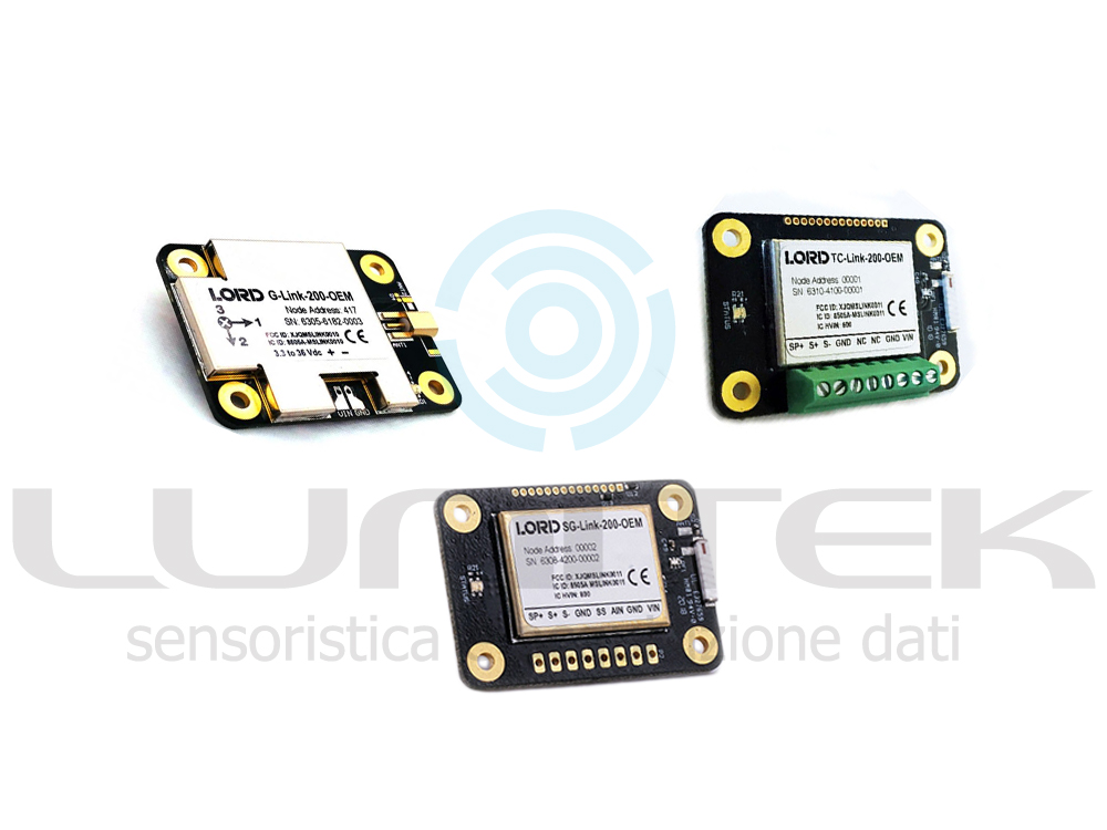
Locata’s hardware uses a number of receivers (top right) and transmitters (bottom right) mounted on a network of ground-based masts (left)

A network of LLs forms a GPS-like constellation that allows signal-based positioning within a serviced area. These networks can cover deep canyons, indoor facilities and other challenging environments where GPS struggles to operate and deliver centimetre-level accuracy with high reliability and guaranteed high repeatability. Locata-based commercial networks can operate as an alternative or an augmentation to GPS.

A Locata network was deployed at IIHS in 2013, with 16 LLs covering both the open and covered test tracks. The network was designed to meet two key requirements: firstly, accuracy of 10 cm or better at 95% confidence, and secondly, a very high degree of repeatability with a service availability (meeting the above accuracy requirement) in excess of 95% of the time. All Locata receivers were expected to time-synchronize with GPS time and use the same coordinate systems as GPS, so any GPS equipment tested, such as built-in navigation systems, can be compared easily.

The IIHS network was designed using Locata tools that simulate network performance for various LL locations and allow the definition of visible/usable areas for each LL. As both IIHS tracks need to be time-synchronized and then to be synchronized with GPS, a single LL was designated as the master for the network. However, the two tracks are separated by a significant height difference, so a chain of LLs was used to bring the TimeLoc from the open track to the lower, covered track. The site topology did not allow good height distribution of LLs, so the optional digital terrain model feature was utilised. The network infrastructure was built and is maintained by IIHS with support from Locata.

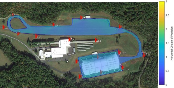
The Locata network at IIHS’s Vehicle Research Centre uses 16 LocataLite transmitters. LL1 was designated as the master for the network. Shading denotes HDOP quality in the serviced area

AB Dynamics

AB Dynamics is the world’s leading supplier of the driving robots used in automotive testing. Driving robots precisely and accurately control vehicle control inputs with a level of repeatability that vastly exceeds that of human test drivers. Historically, driving robots have been used for vehicle dynamics, durability and even crash testing, but when coupled with an accurate position measurement sensor they can execute centimetre-accurate path-following tasks. When developing ADAS the ability to accurately and precisely control vehicle position is key to recreating real-life scenarios.

AB Dynamics’ path-following software is an established and proven technology. Motion data is collected from an inertial measurement unit (IMU) at 100 Hz and fed back to the robot’s path-following controller. This controller employs a speed-dependent look-ahead algorithm that not only maintains the vehicle heading but also allows centimetre accurate path control.

OxTS

OxTS specialises in the design and manufacture of GNSS-aided inertial navigation systems (GNSS/INS) for automotive testing. OxTS systems offer not only centimetre-level position accuracy but also movement data in all vehicle-axes at up to 250 Hz. OxTS’ RT-series of products are used by many of the world’s automotive manufacturers for everything from vehicle dynamics testing to multi-vehicle ADAS testing and validation.

Unlike standalone GNSS automotive systems, which are unable to output data during GNSS blackouts, or are affected by multipath errors, OxTS products are still able to compute position, orientation and velocity measurements because they are built around an inertial measurement unit (IMU) that does not rely on external signals.

However, systems that rely on inertial measurements only are also prone to accumulated position estimate errors, or drift, with time. In OxTS’ products these errors are mitigated by the GNSS input, and several other inputs can be used alongside the IMU platform to create a hybrid system where each technology addresses weaknesses in others. The end result is an accurate and reliable measurement system that works in challenging real-world conditions. This makes it particularly suitable for robotic applications where a sudden loss of position information, or sudden jumps in location or heading, can have serious implications.

When the OxTS system is configured to work with the Locata system, the built-in GNSS information is replaced by measurement input from the Locata receiver to produce accurate and reliable measurements while maintaining excellent position accuracy. Data is output via Ethernet and CAN to be used by other equipment, such as driving robots, or logged. Raw measurements are also logged internally to be downloaded for post-processing in order to test different scenarios or make other changes.

Automated platform demonstration

In October and November of 2017 IIHS, in partnership with Locata, OxTS and AB Dynamics, conducted a demonstration of its all-weather test facility. For this demonstration, an RT1003 GNSS-INS was used to receive PVT data from the LL receiver instead of the RT’s GNSS receiver. No specific configuration was needed to interface the RT with the Locata receiver and the setup could be run interchangeably with either a GNSS or a Locata receiver. Both the RT1003 and the Locata receiver were mounted on one of the vehicle’s rear seats.

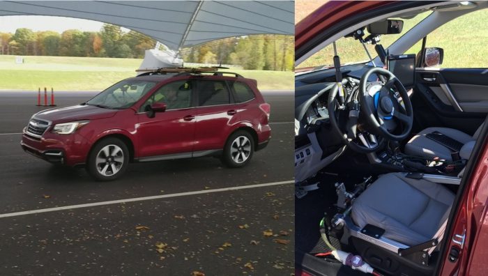
Test vehicle’s manual controls remained accessible to the driver despite AB Dynamics’ driving robot. OxTS RT1003 GNSS-INS and Locata receiver were mounted on the rear seat (not shown)

AB Dynamics provided a flexible driving robot drop-in kit that was quickly installed without modifications to the vehicle. Even with the robot installed, the steering wheel, throttle and brakes remain accessible to the driver. At the heart of the driving robot is a dedicated real-time controller, which coordinates the steering and pedal robots and captures data at speeds of up to 1000 Hz.

The Locata antenna was fixed to a roof rack-mounted ground plane, approximately aligned with the centreline of the vehicle. A second Locata antenna was connected to a second Locata receiver to be used for post-processing accuracy analysis of the fixed baseline between the two antennas. This baseline was then used as the truth for Locata-only post-processing accuracy analysis.

Test Procedure

The test vehicle was driven in various driving patterns on both test tracks. Double lane changes (DLCs), conducted on both tracks, resemble the driving pattern needed for testing most collision-avoidance and lane-change features, while an S-curve driving pattern was used to simulate IIHS’s headlight evaluations.

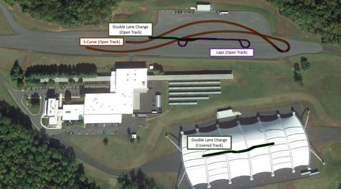
Double lane changes, S-curves and laps were performed on IIHS’s open track. Double lane changes alone were carried out on the covered track

Analysis and results

Data analysis from two full days of testing focused on the accuracy and repeatability of the automated test setup as a complete system first and then Locata alone.

The foundation for a highly repeatable control system with positioning accuracy is a highly reliable Locata network that delivers repeatable DOPs and a number of ranging signals at any given track location. Repeatability of the numbers of LLs seen and the HDOPs were investigated for this purpose.

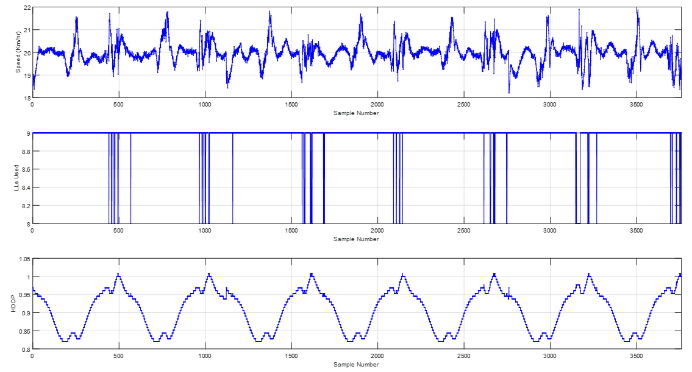
During the five repeats of the DLCs conducted at 45 km/h on the covered track the number of LLs seen remained constant at seven, as expected.

Double lane change data analysis showed that the number of visible LLs remained constant at seven (top). Bottom data trace shows HDOP count


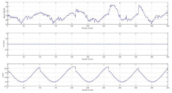
For the 20 km/h lap scenario on the open track, the number of LLs varied between eight and nine, with the drop occurring at one end of the lap.

Variations in timings of the LL visibility drop on the open track were due to varying vehicle speed in turns; bottom data trace shows the HDOP count


Analysis of the 48 DLC repetitions from the covered track, carried out at a range of speeds from 10 to 45 km/h, revealed a high level of repeatability. In straight segments the control system was able to repeat all the runs with less than 4 cm of mean deviation. A mean deviation of 5 cm was seen in the turns due to the range of speeds and the increasing lateral acceleration at higher speeds. The standard deviation also followed the same pattern, remaining below 3 cm during the straight-line segments and increasing up to 5 cm during the turns. A standard deviation of less than 2.5 cm was seen throughout all parts of the scenario, demonstrating that the Locata/OxTS/AB Dynamics automated control system maintained a run-to-run mean deviation of 5 cm or better and a standard deviation of 2 cm during straight-line driving.

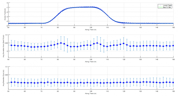
Top subplot shows best-fit path from data average of 48 DLC repetitions on the covered track; Middle subplot shows mean and standard deviation of cross-track error of all repetitions compared with best-fit path; bottom subplot shows mean and standard deviation of baseline error measured between the two Locarta antennas mounted on the vehicle


Locata baseline error from repetitions of all scenarios was then used to estimate a probability distribution function (PDF) to assess the Locata positioning system performance alone. This included close to 180,000 data points from around five hours of automated driving. This baseline error PDF gives a Locata positioning accuracy of 2.8 cm at 95% and 5.6 cm at 99.7%, which is far in excess of the IIHS requirement of 10 cm at 95%.

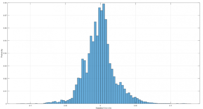
Probability distribution function of baseline error was far in excess of IIHS requirements

Conclusion

With the addition of a covered test track, the Insurance Institute for Highway Safety needed an accurate and repeatable measurement system. Locata was able to install a local network of LocataLites to form a GPS-like constellation of transmitters to provide centimetre-level accuracy. With the positioning solution from Locata and an inertial measurement solution from OxTS, AB Dynamics was able to demonstrate accurate and repeatable testing with an automated driving robot.


Per maggiori informazioni contattaci: https://www.lunitek.it/contatta-sensoristica-e-acquisizione-dati/

Novembre 28, 2018 / by / in
PPM TEST – Airbus in Germania opta per il sistema a fibra ottica Sentinel 3 RF

Airbus in Germany chooses Sentinel 3 RF over fibre system

PPM are pleased to announce the that another European Airbus site has chosen Sentinel 3. Airbus Defence and Spaceheadquarters in Ottobrunn, near Munich. have chosen to integrate the Sentinel 3 RF over fibre system to their data acquisition platform.

About Airbus Munich

Airbus are a partner in the Eurofighter Typhoon consortium which also includes BAe Systems and Leonardo. Other activities at the site include development and manufacture of Arian 5 rocket engines and production of solar panels for satellites. NASA’s James Webb Space Telescope was built in the Ottobrunn site which also houses some of Airbus’ support functions such as Airbus cyber security, information management and finance.

Saving time and improving accuracy.

Sentinel 3 is the worlds most advanced RF over fibre system for EMC testing. The system was designed for rapid and flexible deployment, from remote transmitters through to the controller and receiver chassis. Upgrading to a Sentinel 3 system is anticipated to save a significant amount of setup time. Furthermore, features such as automatic thermal temperature compensation and 0.25dB accuracy specification are designed to improve measurement results.

PPM-supported Integration

The Sentinel 3 system has been very well received by companies involved in the Eurofighter programme,” says Dr Martin Ryan – managing director of PPM. “We are very pleased to be supporting with another Airbus site with Sentinel 3. As always, our software team are ready to help with integration of Sentinel 3 into an existing data acquisition platform which typically might include current probes, E-field probes and RF amplifiers.

About PPM Test

PPM Test is a division of pulse power and measurement Ltd. which has been manufacturing RF over fibre systems since 1995. PPM have supplied RF over fibre to some of the world’s largest manufacturers of aircraft, military and civilian vehicles. The company develops and manufactures in Swindon, UK.


Per maggiori informazioni contattaci: https://www.lunitek.it/contatta-sensoristica-e-acquisizione-dati/

Novembre 23, 2018 / by / in
PPM TEST – Aircraft EMC testing (part 2)

HIRF Test Methodology

The final stage of aircraft clearance may involve limited illumination of the aircraft with threat level RF fields, typically over the range 10 kHz – 18 GHz.  As an alternative approach, with lower facility costs than for testing the total aircraft with threat simulators, the following methodology is being increasingly used

Measure the coupling of EM energy (transfer function)

Measure the coupling of EM energy (transfer function) into the interior of the aircraft over the total frequency band of all the environments by illuminating the aircraft with low level swept continuous wave (CW) radiated fields. These measurements are normally made in “free field” conditions. Where the transfer function is in terms of the external field to the internally induced cable bundle currents it is known as the Low Level Swept Current (LLSC) test (Figure 1) and when it is in terms of the external field to the internally induced fields it is known as the Low Level Swept Field (LLSF) test (Figure 2).

FIG.1 – Test Arrangement for the LLSC Test (nose antenna omitted)


FIG.2 – Test arrangement for the LLSF test

STEP 1 – Compute currents or internal fields from coupling measurements

Use suitable signal processing algorithms and compute from the coupling measurements the currents (100 MHz) at the equipment’s location, that would be induced by the HIRF environments on the wiring systems.

STEP 2 – Directly inject predicted threat currents or irradiate the equipment and its wiring

Directly inject the predicted threat currents on the wiring systems, or at higher frequencies (>400MHz), irradiate the equipment and its wiring being assessed with predicted threat fields. Appropriate modulation is applied to simulate emitter parameters. This testing can be applied at system rig level (alternatively termed the systems integration facility), providing the rig is an accurate representation of the aircraft system.

STEP 3 – Use current probes and broadband antennas

Cable bundle currents can be measured using small ferrite current transformers or probes.  The internal fields can be measured using small broadband antennas, such as the “Top Hat” biconical 1- 18 GHz receive antenna shown in Figure 2. Signals from the current probes/antennas are coupled back to the remote instrumentation using analogue FOLs to as high a frequency as possible.  Multi-channel FOLs, such as the PPM Sentinel 3 cover frequencies up to 3GHz. Above this frequency, cables are used with great care to ensure they don’t compromise the integrity of the airframe shielding being assessed.

The future of HIRF testing with FOLs

Future fibre optic technology will likely permit reliable FOLs to be developed to cover the full low level swept coupling range of 10kHz to 18GHz. This would dramatically improve the measurement dynamic range as such high frequency FOLs would remove the cable losses which become large above 1GHz due to the cable lengths involved. As an example, even low-loss microwave signal cables have loss figures of typically 1 dB/metre at 18GHz.


Per maggiori informazioni contattaci: https://www.lunitek.it/contatta-sensoristica-e-acquisizione-dati/

Novembre 22, 2018 / by / in
PPM TEST – Aircraft EMC testing

Avoiding instrumentation interference and signal losses at high frequencies

As part of an aircraft’s certification for flight, aircraft must demonstrate safe operation within a range of environmental conditions. This includes Electromagnetic Environmental Effects (E3) which, for civil aircraft, include High Intensity Radiated Fields (HIRF) and Lightning. Both HIRF and lightning testing involves either (i) high level whole aircraft testing or (ii) a hybrid test method of low level aircraft testing with high level equipment testing.

For either test method, fibre optic links (FOLs) are essential to prevent compromising the measurements. For example, during low level swept current and field measurements, FOLs are employed to provide signal gain and isolation from the generated EM environment, typically from 10kHz to 1GHz.

Prevent instrumentation influencing the aircraft’s transfer impedance

Instrumentation should not influence the aircraft’s transfer impedance whilst it is exposed to RF fields or simulated lightning – for example, currents that degrade the airframe shielding. Interconnecting cables that pass from the external environment to the internal aircraft environment will impact measurements, for example RF current can flow on the cable shields. It is important therefore that signal cables are not used to connect the external instrumentation to the field/current/voltage probes installed within the aircraft, whilst performing frequency or time domain measurements. This is particularly significant over the 10kHz to 1GHz frequency range, where cable coupling dominates the leakage mechanism into the aircraft under test.

Avoiding signal loss at high frequencies

The external instrumentation must be outside the measurement area which with large aircraft may lead to a separation distance of tens’s of metres. Signal loss then becomes a factor at higher frequencies. Such signal loss is also avoided by the use of a FOLs. A typical aircraft low level swept current measurement would require signal cables of 40 to 50 metres, introducing significant losses. FOLs are typically used with 100 or 200m link lengths, permitting signals to be coupled from the transducers installed on the aircraft to the measurement equipment for even large transporter/passenger aircraft, requiring fibre lengths of over 100m.


Per maggiori informazioni contattaci: https://www.lunitek.it/contatta-sensoristica-e-acquisizione-dati/

Novembre 20, 2018 / by / in
ELASTISENSE – Kit portatile per misurazioni con sensori di spostamento elastomerici

PTK Portable Test Kit with Elastomeric Displacement Sensors


The PTK enables easy yet precise displacement measurements of a system or tool, with up to two sensors, allowing system characterization and monitoring.

PTK is a Plug and Play system consisting of:
• 2x elastomeric displacement sensors
• 1x data acquisition unit
• 2x sensor cables
• 1x charging cable
• 1x USB cable to connect to a PC
• 1x User Interface software

Our displacement sensors are designed to detect and show micron-level displacements. By using two sensors the PTK can also provide relative displacement differences between two signals.

The displacement sensors are able to tolerate aggressive mechanical environments, and are therefore uniquely suited for complete cycle measurements of processes like stamping and deep drawing. Here the PTK allows characterization of a complete tool cycle, as well as detection of any abnormalities such as lack of parallelism, slugs and similar.

The User Interface screen shot below shows a PTK measurement of a stamping tool where slug and lack of parallelism of the tool were characterized.

0.5mm obstruction shown between 2nd and 3rd cycle as highlighted. The difference in peak height indicates a Lack of parallelism between the two measuring points of the sensors.

What can the PTK do for you?
The PTK is a cost competitive test instrument, for assessing the behaviour of your processes and tools, before investing in a full, integrated monitoring system in your production environment. The PTK also enables you to characterize the dynamics of your machines and tools at different operation conditions to provide data/driven optimisation.

The main benefits of PTK are:
• Easy to set up and use – Plug and Play
• Measure and monitor all 360 degrees of a cyclical process – e.g. strokes of a stamping or deep drawing tool
• Standard feature for saving measured data for post-processing and presentation
• Update frequency (max. 1000 samples/s)
• Option for detecting peaks and valleys in the measured signal

FIG.3 – Installation example of the PTK in a system

The software associated with PTK is for Windows based devices. The software displays sensor measurements in real time as well as saving the data to a .txt file. The data can therefore be imported into Excel for analysis, presentation etc.

FIG.4 – Data file example with 10 recordings/s

The graph below shows a real application example where a PTK was installed in a progressive stamping tool to measure tools characteristics in presence of an obstruction (slug). The example shows a change in tool stroke characteristic due to a 0.03mm slug.

The sensor technology
Being capacitive and highly elastic, the Electroactive Polymer (EAP) core is the highly accurate central element of our sensors. Being made solely from rubber also makes the sensor intrinsically tolerant of misalignments and high vibration levels.

Per maggiori informazioni contattaci: https://www.lunitek.it/contatta-sensoristica-e-acquisizione-dati/

Novembre 19, 2018 / by / in
LORD MICROSTRAIN – Espande la serie di nodi wireless per acquisizione dati con soluzioni OEM facili da integrare

LORD Sensing Microstrain Expands Remote Sensing Options with Easy to Implement Solutions

OEMS now have a quick option for embedding high quality wireless data into their applications

CARY, N.C. – LORD Sensing, MicroStrain — a global leader in sensing systems — has announced the addition of two wireless sensors that enable OEMs to remotely collect data from a range of sensor types.
“Building a wireless temperature data acquisition system can be difficult and time consuming,” said Chris Arnold, LORD Sensing Product Manager. “The TC-Link®-200-OEM ,the SG-Link®-200-OEM and the G-Link®-200-OEM sensors now allow customers to quickly and easily integrate wireless data acquisition into their product without worrying about signal conditioning and radio design.”
Already proven as a solution for electric vehicle fuel cell condition monitoring, the TC-Link®-200-OEM allows users to remotely collect data from a range of temperature sensor types including thermocouples, resistance thermometer, and thermistors. The technology was developed for use with common temperature probes, includes cold junction compensation for thermocouples and linearization of all temperature measurements. The nodes support high resolution, low noise data collection at rates up to 128Hz. The new sensor is miniature, light weight and designed to be easily embedded. Many of the same features found on other LORD wireless products are included on the TC-Link®-200-OEM.
Intended to be used with strain gauges (Wheatstone bridge input), SG-Link®-200-OEM was an early adopter for monitoring mining equipment. The sensor also allows users to remotely collect data from a range of sensor types, including strain gauges, pressure transducers and accelerometers. The node includes on-board shunt calibration for easy in-situ strain gauge calibration and supports high resolution, low noise data collection from one differential and one single-ended input channel at sample rates up to 1kHz. A digital input allows compatibility with a hall effect sensor for reporting RPM and total pulses, making the sensor ideal for many torque sensing applications.

The G-Link-200-OEM has an on-board triaxial accelerometer that allows high-resolution data acquisition with extremely low noise and drift. Additionally, derived vibration parameters allow for long-term monitoring of key performance indicators while maximizing battery life. Users can easily program nodes for continuous, periodic burst, or event-triggered sampling with the SensorConnect software. The optional web-based SensorCloud interface optimizes data aggregation, analysis, presentation, and alerts for sensor data from remote networks.

Both wireless OEM sensing solutions are compact in size and offer low power operation, making them well suited for battery powered applications.
Novembre 2, 2018 / by / in